|
 |
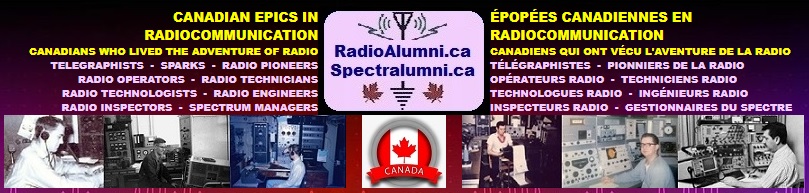
An HF array at the Ashton,
Ont.,
field site used to study the lowest part of the ionosphere (the D region) by observing HF waves partially reflected from the region. The array consists of a grid of 40 half-wave dipoles suspended some 90 ft. from
the ground by 25 wooden poles. The large
physical size of this array compared to those at higher frequencies is dictated by
wavelength (at 3 MHz a wavelength is 100 meters; at 300 MHz it is one meter).
The D region, which strongly influences
the propagation of VLF to HF signals, was extensively studied by CRC using this facility from about 1964 to
1974. |
|
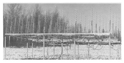 |
This UHF antenna,
which transmits
and receives signals at 450 MHz, is used for ionospheric studies at the Ashton,
Ont.,
field
station. |
|
|
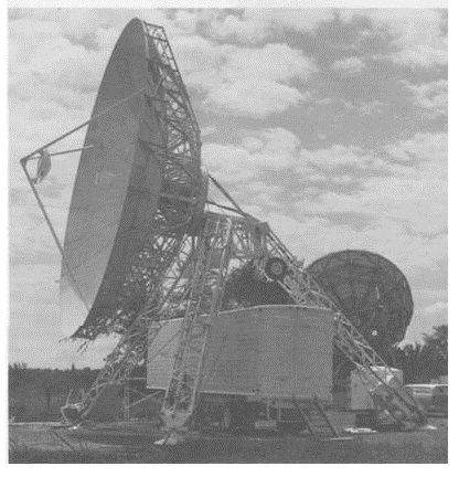
To the left in the
background is an array of cross yagis, which provides a back-up for reception of
signals from the Isis satellites at 136 MHz and provides command signals at 148 MHz
to the Isis satellites. |
|
 |
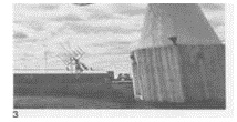
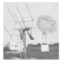
A VHF-UHF antenna, 60-feet in' diameter, with a parabolic reflector dish, which operates in the
136 MHz and 400 MHz band and is used
for telemetry with the
Alouette
and Isis satellites, the first Canadian, ionospheric satellites. |
|
 |
Two terminals
constructed and operated by the Communications Research Centre. The
land-mobile terminal on the left has adjustable transmit and receive yagi antennas. |
|
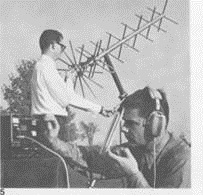 |
View of the UHF
small terminal, with radio equipment in foreground and antenna in
background. Ron Yank is shown operating the radio equipment, with Dave
Barlow pointing the antenna in the direction of the satellite. The antenna
was used
in Tacsatcom experiments. The portable earth station was used for voice and data communications with the
satellite.
It was also used in the 1970 royal tour of the
North by reporters sending their reports south. |
|
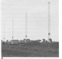 |
The high frequency direction findings (HFDF) array near Richmond,
Ont.
This
array consists of 94 individual elements in two arms some 243 m and 2134 m
long. (The photo shows the elements of the longer arm.) These arms are
at right angles to each other in the form
of a cross. An individual receiver is provided for each element. These,
together with a computer that performs control, calibration and data processing functions, are housed in a lab at the centre of the
array. The lab is underground to avoid
interference with the array.
The
facility is used to research the variations in direction of arrival of HF signals transmitted from known locations. Such
knowledge is required to refine and improve existing direction finding techniques.
|
|
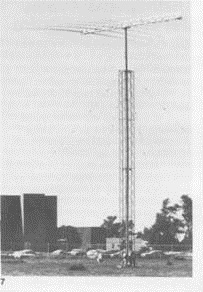 |
Log periodic dipole
antenna used for
HF (6 to 40 MHz) communications at CRC.
This antenna is rotatable by means of an
electric motor at the base of the tower
which is under remote control. |
|
 |
This 10-metre
antenna was used in
teleconferencing demonstrations between
France and Canada with the French-German
Symphonie
satellite. It transmits audio-video signals at 6 GHz and
receives at the 4 GHz level. The antenna is portable and self-contained. The wheels, part of the running gear,
can be
seen on the back leg of the antenna's tripod. |
|
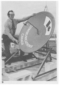 |
This 1.2-metre
parabolic dish has been used in the Hermes satellite experiments. The
portable earth terminal receives TV signals only. |
|
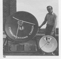 |
These
two satellite earth terminals, 1.2 metres and 0.6 metres in diameter, were also
used with the CTS experiments. The portable TV-receive- - only
terminals were designed to be prototypes of a terminal that could be mass
produced for about the cost of a color
TV set. |
|
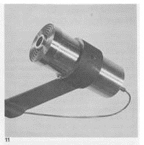 |
A close-up of the
outdoor unit for the prime focus terminals, such as the 0.6-metre terminal
in photo 10. Signals captured by the dish for the satellite transmitter
are focussed into this unit which extends from the centre of the dish and
then fed into a cable which carries the signals to the TV. |
|
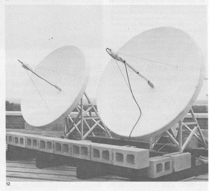 |
These
two 1.6 metre diameter dishes were on loan from Phillips of the Netherlands and the Mullard Research Centre in England. The dishes were the
first attempt by Phillips at development of a TV-receive-only terminal and were
used in Hermes demonstrations.
|